
Introduction
In today’s rapidly evolving engineering landscape, the complexity of modern systems demands more sophisticated approaches to design, verification, and validation. Traditional document-based systems engineering methods struggle to maintain traceability, manage interdependencies, and ensure consistency across large-scale projects. Model-Based Systems Engineering (MBSE) has emerged as the solution to these challenges, providing a formalized, digital backbone for system development.
SysML v2 represents a paradigm shift in how systems engineers capture, communicate, and validate system designs. Unlike its predecessor, SysML v2 offers a more rigorous, computationally-sound foundation that bridges the gap between abstract requirements and concrete implementations. This case study examines a practical Vehicle System Example to demonstrate how SysML v2’s core concepts—the three pillars of MBSE, the separation of problem and solution spaces, and the sophisticated relationship management between definitions and usages—create a robust framework for modern systems engineering.
Through this comprehensive exploration, we will uncover how a simple electric vehicle acceleration requirement transforms from a stakeholder need into a fully traceable, verifiable system model. This journey illustrates not just the syntax of SysML v2, but the underlying methodologies that make MBSE a transformative practice for engineering organizations worldwide.
Comprehensive Guide to SysML v2 Concepts: Foundations of MBSE
This guide explains core Model-Based Systems Engineering (MBSE) foundations using your working VehicleSystemExample code. It maps the syntax of SysML v2 directly to the core modeling methodologies, layers, and relationships shown in the diagram.

1. The Three Pillars of MBSE
Every complex system is modeled using three foundational pillars. Your SysML v2 example organizes these pillars to establish a clean digital thread:
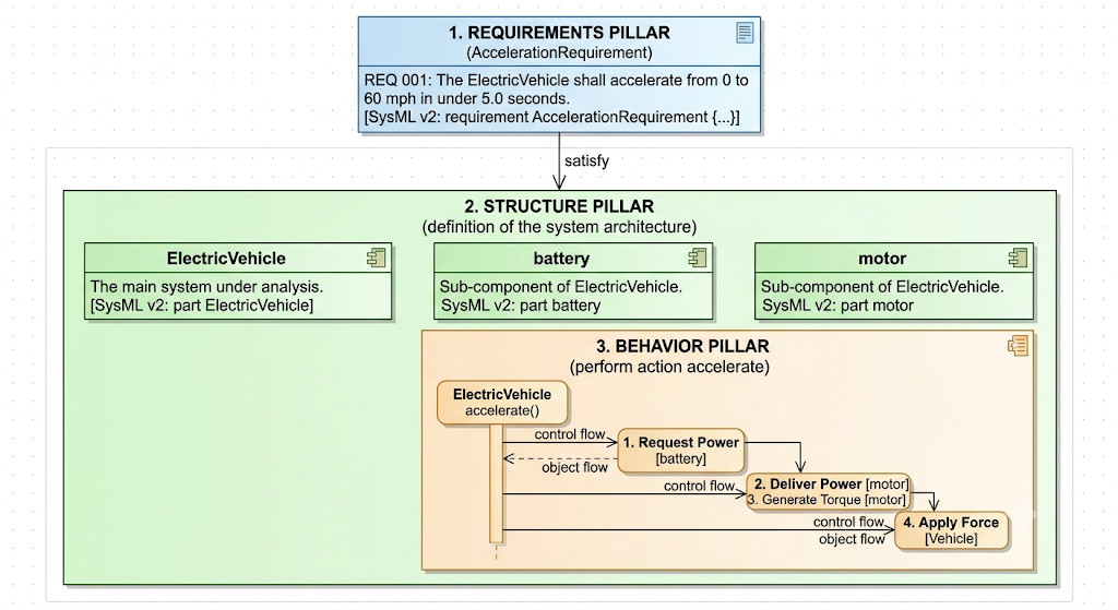
Pillar 1: Requirements (The Problem Space)
Concept: Captures the capabilities, conditions, or performance targets the system must achieve.
Code Implementation:
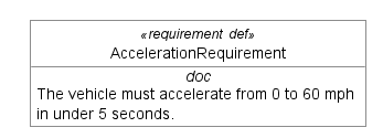
requirement def AccelerationRequirement {
    doc /* The vehicle must accelerate from 0 to 60 mph in under 5 seconds. */
}
Explanation: This establishes the performance contract without prescribing how the vehicle accomplishes it.
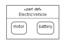
Pillar 2: Structure (The Solution Space)
Concept: Defines the physical, logical, or organizational breakdown of components.
Code Implementation:
Interconnection View:
Default View:
part def ElectricVehicle {
    part battery : Battery;
    part motor : ElectricMotor;
    ...
}
Explanation: This specifies the architectural components (battery and motor) that constitute the physical solution.
Pillar 3: Behavior (The Execution Space)
Concept: Details how the system acts, processes information, or transforms states over time.
Code Implementation:
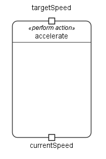
perform action accelerate {
    in targetSpeed;
    out currentSpeed;
}
Explanation: Nested inside the structure, this defines the operational capabilities of the component, transforming inputs into outputs during runtime.
2. Modeling Layers: Problem vs. Solution Space
As noted in the guidance text, models have a minimum of two layers. There is no strict order in which to model them, but they must cross-reference each other to be valuable.
A. The Problem Space
Focuses entirely on stakeholder needs, operational constraints, and requirements. In your example, the requirement def AccelerationRequirement represents this layer. It dictates what the system must achieve.
B. The Solution Space
Focuses on the engineering design that satisfies the problem. The part def ElectricVehicle represents this layer. It details how the system will meet those requirements using structural components and behavioral logic.
Bridging the Spaces
The informal red arrows in your reference diagram represent conceptual relationships. In SysML v2, these are formalized using strict, traceable keywords:
satisfy requirement accelReq : AccelerationRequirement;
This single line connects the Solution Space (ElectricVehicle) back to the Problem Space (AccelerationRequirement), creating an audit trail for verification.
3. Structural Key Relationships
The core of the reference diagram outlines how definitions and usages interact in SysML v2. Your working code implements these exact principles:
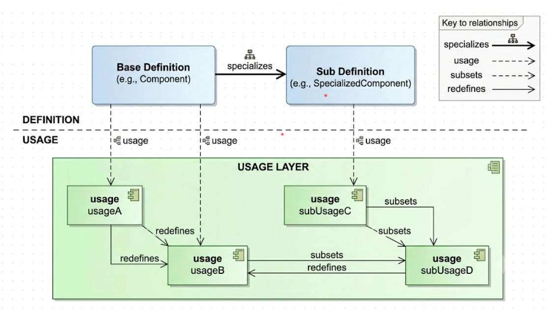
  [ Definition ]  ────────── (specializes) ──────────►  [ SubDef ]
  (e.g., Component)                                   (e.g., SpecializedComponent)
          │                                                   │
       (usage)                                             (usage)
          ▼                                                   ▼
     [ usage ]    ◄─── (subsets) / (redefines) ───────   [ subUsage ]
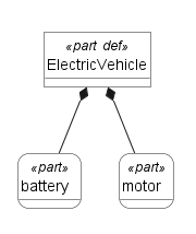
Definition vs. Usage
Definition: A reusable blueprint or template. It does not exist as a physical object yet.
Code example: part def ElectricVehicle; (The generic blueprint for all such vehicles).
Usage: A specific occurrence, instance, or component part generated from that blueprint.
Code example: part battery : Battery; (A specific instance named battery that is built from the blueprint Battery).
The 5 Graph Relationships
Your code sets up the foundation to use all five relational pathways from the diagram:
-
Definition → usage (:): Establishing an instance from a blueprint.
-
Example:
part motor : ElectricMotor;binds a structural usage to its type definition.
-
-
Definition → SubDef (specializes): Creating a child blueprint from a parent blueprint.
-
Example: If you created
part def PerformanceEV specializes ElectricVehicle;, the new definition inherits all parts (battery, motor) and behaviors (accelerate) from the parent definition.
-
-
SubDef → subUsage (usage 🙂: Instantiating a component from a specialized sub-definition.
-
Example: A specialized car would contain a specialized sub-usage component inside it.
-
-
subUsage → usage (subsets :>): Indicating that a specific collection of instances is part of a broader parent collection.
-
subUsage → usage (redefines :>>): Completely replacing or refining an inherited parent usage with a specialized sub-usage.
-
Example: If a PerformanceEV needs a HighOutputMotor instead of the standard base motor, you would declare:
part highOutputMotor : HighOutputMotor redefines motor;. This satisfies both subsets and redefines simultaneously.
-
Practical Application: Building Traceable Systems
The VehicleSystemExample demonstrates more than just syntax—it showcases a methodology for creating auditable, maintainable system models. By separating concerns across the three pillars and maintaining clear relationships between problem and solution spaces, engineering teams can:
-
Track Requirements Coverage: Every structural element and behavioral action can be traced back to specific requirements, ensuring nothing is built without justification.
-
Manage Change Impact: When requirements evolve, the model’s relationships immediately reveal which components and behaviors require modification.
-
Enable Verification: The clear separation between what the system must do (requirements) and how it does it (structure and behavior) creates natural verification checkpoints.
-
Support Reuse: Definitions serve as reusable templates across multiple projects, while specializations allow for domain-specific adaptations without duplicating effort.
Advanced Modeling Considerations
As systems grow in complexity, the foundational concepts demonstrated here scale to accommodate sophisticated modeling needs:
Allocation Strategies: Beyond the basic satisfy relationship, SysML v2 supports allocate relationships that map behavioral actions to specific structural components, enabling detailed resource analysis and performance modeling.
Multi-Layer Architectures: While the minimum model includes problem and solution spaces, complex systems often benefit from additional layers such as conceptual architecture, logical design, and physical implementation, each with their own traceability chains.
Variability Management: Through specializes and redefines relationships, a single base model can support multiple product variants, configuration options, and evolutionary iterations while maintaining a coherent digital thread.
Conclusion
The transition from document-based to model-based systems engineering represents more than a change in tools—it embodies a fundamental shift in how we conceive, design, and validate complex systems. Through the VehicleSystemExample, we have explored how SysML v2’s three pillars (Requirements, Structure, and Behavior) create a comprehensive framework that captures not just what a system is, but why it exists and how it operates.
The separation of problem and solution spaces, formalized through rigorous definition-usage relationships, provides engineering teams with unprecedented clarity and traceability. Every requirement finds its realization in structural components and behavioral actions; every design element traces back to stakeholder needs. This bidirectional traceability transforms systems engineering from an art into a disciplined, verifiable practice.
As organizations face increasingly complex challenges—from autonomous vehicles to smart infrastructure—the methodologies demonstrated in this case study become not just beneficial, but essential. SysML v2 provides the semantic precision and computational foundation needed to manage this complexity, while the underlying MBSE principles ensure that models remain aligned with real-world requirements throughout the system lifecycle.
The journey from a simple acceleration requirement to a fully specified electric vehicle model illustrates the power of systematic, model-based thinking. By embracing these concepts, engineering organizations can build systems that are not only functionally correct but also adaptable, verifiable, and aligned with stakeholder expectations from conception through deployment and beyond.
References
-
SysML v2 Specification: Official OMG SysML Version 2.0 specification defining the language syntax, semantics, and modeling constructs for systems engineering.
-
Model-Based Systems Engineering Fundamentals: Comprehensive guide to MBSE principles, methodologies, and best practices for implementing model-based approaches in systems engineering.
-
INCOSE Systems Engineering Handbook: Authoritative resource on systems engineering processes, lifecycle management, and the integration of MBSE practices.
-
SysML Distilled: A Brief Guide to the Systems Modeling Language: Practical introduction to SysML concepts, diagrams, and applications in real-world systems engineering projects.
-
Applied Model-Based Systems Engineering: Using SysML for Complex System Design: Advanced techniques for implementing MBSE, including requirement traceability, architectural design, and verification strategies.
-
Digital Engineering Transformation: From Documents to Models: Exploration of organizational change management and technical strategies for transitioning to model-based engineering practices.
-
Requirements Engineering and Management for MBSE: Specialized focus on capturing, analyzing, and tracing requirements within model-based systems engineering frameworks.
-
SysML v2 Pilot Implementation Guide: Practical guidance for early adopters implementing SysML v2, including tool selection, migration strategies, and common pitfalls.
Working SysML v2 Example Code:
package VehicleSystemExample {

    // ==========================================
    // 1. REQUIREMENT PILLAR (Problem Space)
    // ==========================================
    requirement def AccelerationRequirement {
        doc /* The vehicle must accelerate from 0 to 60 mph in under 5 seconds. */
    }

    // ==========================================
    // 2. STRUCTURE PILLAR (Solution Space)
    // ==========================================
    part def ElectricVehicle {
        // Structural components (parts)
        part battery : Battery;
        part motor : ElectricMotor;

        // Satisfying the requirement structurally
        satisfy requirement accelReq : AccelerationRequirement;


        // ==========================================
        // 3. BEHAVIOR PILLAR (Execution)
        // ==========================================
        perform action accelerate {
            in targetSpeed;
            out currentSpeed;
        }
    }

    // Definitions for the parts used above
    part def Battery;
    part def ElectricMotor;
}